
|
| |
|
| |
|
|
|
|
|
|
|
|
|
|
|
|
|
| |
 | |
|
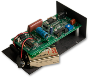
RINGING VOLTAGE GENERATOR Tele-Q is a hand held, battery operated, telephone ringing voltage generator. It will ring any telephone fitted with a modular plug from a set of two 9-volt batteries or optional AC adapter. Tele-Q is shipped in its standard configuration where it produces a ringing voltage simulating the current ITT standard. This means it will ring any telephone that works on a standard telephone line. It is completely ready to use and should provide hours of service with the set of batteries that are already installed. OPERATING INSTRUCTIONS The operating instructions are simple: connect any telephone to the modular jack and press the button. Telephones not fitted with a modular plug can easily be adapted to one. All the parts you need, and probably some helpful advice, are available at your local retail telephone store. The red light (LED) on top of the Tele-Q tells you that it is producing ringing voltage and if batteries need replacement. When batteries are about two thirds depleted, the LED will only flicker briefly when the button is pressed. There is still plenty of operating time left once this begins to happen, however at this point new batteries should be installed if dependable operations is to be insured. MAINTENANCE AND INTERNAL ADJUSTMENTS 250 VOLTS DC AND 120 VOLTS AC ARE EXPOSED IF TELE-Q IS OPERATED OUT OF ITS PLASTIC CASE. THESE VOLTAGES ARE PRESENT ON THE LEFT SIDE OF THE CIRCUIT BOARD WHEN VIEW WITH THE MODULAR JACK POINTING AWAY FROM YOU. NEVER TOUCH CIRCUIT BOARD COMPONENTS WHILE TELE-Q IS ACTIVATED! * * WARNING * * The only tool required to maintain and adjust Tele-Q is a 1/8" blade screwdriver; most any pocketsize screwdriver will do.
 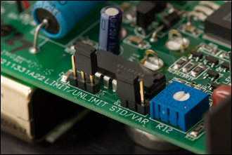 Tele-Q produces a ringing voltage with more power than the Telephone Company. This is because the Phone Company rings your telephone with a sine wave (smoothly oscillating voltage) and Tele-Q does it with a square wave (abruptly oscillating voltage). Since Tele-Q produces more ringing power than is required to ring the bell, a limited duty cycle will still ring the phone and save nearly 1/3 the battery power. In some cases the bell may not sound as strong in the "LIMIT" mode, so a listening test should be conducted to determine if the duty cycle limiter is to be used. The second adjustment is ringing frequency. In the "STD" (standard) mode, Tele-Q generates a 20 Hz ringing voltage, which is the current ITT standard ringing frequency. This means the bell clapper moves back and forth 20 times per second. Changing this frequency will alter the character of the bell's sound; for example a higher frequency can make a standard phone sound British. In addition, some older, foreign, or party line phones will require a different frequency to ring at all. The ringing frequency of Tele-Q can be adjusted between roughly 12 and 60 Hz. To make this adjustment, move the shorting jumper to the "VAR" (variable) position. Now the ringing frequency can be changed with the screwdriver adjustment located just above the shorting jumpers. AC ADAPTER Tele-Q is designed to operate from an external source of 24-volt DC power. This power is applied through the 2.5-mm DC power jack on the front of Tele-Q. An AC adapter for this application is available for CEI or your Tele-Q dealer. THE MODULAR CONNECTOR All the functions of Tele-Q are addressable through the modular jack on the front of the unit. The following provides technical information for the enterprising technician who wants to adapt Tele-Q to his own specific requirements. Normal telephone service is provided through a RJ-11 6-4 modular connector. This connector is a 6-position plug or jack with 4 conductors loaded into it. Tele-Q is fitted with a 6-6 modular jack which means there are two conductors that are never used when connected to a normal telephone. These conductors bear power from the batteries and a remote control line that when brought to ground, will activate Tele-Q. The pins of a modular connector are literally numbered inside out. If you view a modular plug with the clip away from you, the pins are numbered from left to right: 5 - 3 - 1 - 2 - 4 - 6. In other words, the first pair, 1 & 2, are in the center, the second pair, 3 & 4, surround the first pair, and likewise, the last pair, 5 & 6, are on the outside. Tele-Q generates a single ended ringing voltage on pin 1 referred to ground (floating) on pin 2. Pins 3 & 4 are user definable. Pin 6 delivers primary power and pin 5 is the remote control line. Pins 3 & 4 are normally not connected because in some phone services these wires (yellow & black) are often tied or grounded. With this in mind, you can add soldered jumpers to the circuit board which will connect one of two remote functions to this pair. On the left side of the circuit board you will find solder pads marked 3 & C. 3 is pin 3 of the modular jack and C is the remote control line connected to pin 6. On the right side of the circuit board you will find solder pads marked B, 4, and A. 4 is pin 4 of the modular jack and A & B allow remote frequency control of Tele-Q. To remotely control frequency, remove the STD/VAR shorting jumper completely and bring out A & B on pins 3 & 4. A variable resistance between 10K and 60K across this pair will provide roughly the same degree of control as the circuit board adjustment. To remotely activate Tele-Q through a 4-wire line, solder a jumper between 3 & C. Now whenever pin 3 is brought to ground, pin 2, Tele-Q will be activated. |
CEI, Inc.
P.O. Box 51
Decorah, Iowa 52101
563.382.5659
mail@tele-q.com